Overview
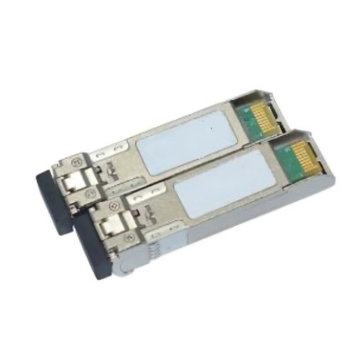
Emissions And Stack single mode transceiver is small form factor pluggable module for duplex optical data communications such as 10GBASE-LR/LW defined by IEEE 802.3ae. It is with the SFP+ 20-pin connector to allow hot plug capability.
The EMSSPBTP-112 (A) module is designed for single mode fiber and operates at a nominal wavelength of 1270nm. EMSSPBTp-112 (B) module is designed for single mode fiber and operates at a nominal wavelength of 1330nm. The transmitter section uses a multiple quantum well DFB, which is class 1 laser compliant according to International Safety Standard IEC-60825.
The receiver section uses an integrated InGaAs detector preamplifier (IDP) mounted in an optical header and a limiting post-amplifier IC.
Features
- Simplex LC Connector Bi-Directional SFP+ Optical Transceiver
- Compliant with SFF-8431,SFF-8432 and IEE802.3ae
- Up to 10km on 9/125um SMF
- Two types:
- A:1270nm DFB Laser transmitter,1330nm receiver
- B:1330nm DFB Laser transmitter,1270nm receiver
- Digital Diagnostic SFF-8472 Compliant
- Operating case temperature -0 ~ 70 °C
- RoHS6 compliant (lead free)
Applications
- 10GBASE-LR at 10.3125Gbps
- Other Optical Links
Technical Specifications
Absolute Maximum Ratings
| Parameters | Symbol | Min. | Max. | Unit |
| Supply Voltage | VCC | -0.5 | +3.6 | V |
| Storage Temperature | Tc | -40 | +85 | °C |
| Operating Case Temperature | Tc | -40 | +85 | °C |
| Relative Humidity | RH | 0 | 85 | % |
Recommended Operating Conditions
| Parameter | Symbol | Min | Typical | Max | Unit |
| Supply Voltage | Vcc | 3.13 | 3.3 | 3.46 | V |
| Supply current1] | Icc | – | 200 | 300 | mA |
| Case Operating Temperature (Commercial) | Tcase | 0 | +70 | ºC | |
| Case Operating Temperature (Industrial) | -45 | +85 | ºC | ||
| Notes:
1. Supply current is shared between VCCTX and VCCRX. 2. In-rush is defined as current level above steady state current requirements. |
|||||
Electrical characteristics
| Parameter | Symbol | Min. | Typical | Max | Unit | Ref. |
| Supply Voltage | VCC | 3.00 | 3.60 | V | 1 | |
| Supply Voltage | Icc | 200 | 300 | mA | 1 | |
| Transmitter | ||||||
| Input differential impedance | Rin | 100 | Ω | 2 | ||
| Single ended data input swing | Vin,pp | 150 | 1200 | mVpp | ||
| Transmit Disable Voltage | VD | 2 | VCC | V | ||
| Transmit Enable Voltage | VEN | Vee | Vee+0.8 | V | 3 | |
| Receiver | ||||||
| Output differential impedance | Rout | 100 | Ω | 2 | ||
| Single ended data output swing | Vout,pp | 300 | 700 | mV | 4 | |
| LOS Fault | VLOS fault | 2 | VCCHOST | V | 5 | |
| LOS Normal | VLOS norm | Vee | Vee+0.8 | V | 5 | |
| Notes:
1. Module power consumption never exceeds 1W. 2. AC coupled. 3. Or open circuit. 4. Into 100 ohm differential termination. 5. LOS is LVTTL. Logic 0 indicates normal operation; logic 1 indicates no signal detected. |
||||||
Optical characteristics EMSSPBTp-112 (A), 1270 DFB & PIN/TIA
| Parameter | Symbol | Min. | Typical | Max | Unit | Ref. |
| Transmitter | ||||||
| Optical Wavelength | λC | 1260 | 1270 | 1280 | nm | |
| Side Mode Suppress Ratio | SMSR | 30 | dB | |||
| Spectral Width(-20dB) | Δλ | 1 | nm | |||
| Average Output Power | Pop | -8.2 | 0.5 | dBm | 1,2 | |
| Extinction Ratio | ER | 3.5 | dB | |||
| Eye Mask | Compliant with IEEE 802.3 | |||||
| Receiver | ||||||
| Average Receiver Power | RSENS | -14.4 | dBm | 2,3 | ||
| Receiver Overload | PMAX | +0.5 | dBm | |||
| Centre Wavelength | λC | 1320 | 1340 | nm | ||
| LOS De-Assert | LOSD | -15 | dBm | |||
| LOS Assert | LOSA | -30 | dBm | |||
| LOS Hysteresis | 0.5 | dB | ||||
Optical characteristics EMSSPBTp-112 (B), 1330 DFB & PIN/TIA
| Parameter | Symbol | Min. | Typical | Max | Unit | Ref. |
| Transmitter | ||||||
| Optical Wavelength | λC | 1320 | 1330 | 1340 | nm | |
| Side Mode Suppress Ratio | SMSR | 30 | dB | |||
| Spectral Width(-20dB) | Δλ | 1 | nm | |||
| Average Output Power | Pop | -8.2 | 0.5 | dBm | 1,2 | |
| Extinction Ratio | ER | 3.5 | dB | |||
| Eye Mask | Compliant with IEEE 802.3 | |||||
| Receiver | ||||||
| Average Receiver Power | RSENS | -14.1 | dBm | 2,3 | ||
| Receiver Overload | PMAX | +0.5 | dBm | |||
| Centre Wavelength | λC | 1260 | 1270 | nm | ||
| LOS De-Assert | LOSD | -15 | dBm | |||
| LOS Assert | LOSA | -30 | dBm | |||
| LOS Hysteresis | 0.5 | dB | ||||
Pin definition
| Pin | Symbol | Name/Description |
| 1 | VEET [1] | Transmitter Ground |
| 2 | Tx_FAULT [2] | Transmitter Fault |
| 3 | Tx_DIS [3] | Transmitter Disable. Laser output disabled on high or open |
| 4 | SDA [2] | 2-wire Serial Interface Data Line |
| 5 | SCL [2] | 2-wire Serial Interface Clock Line |
| 6 | MOD_ABS [4] | Module Absent. Grounded within the module |
| 7 | RS0 [5] | RS0 for Rate Select: Open or Low = Module supports ≤4.25Gbps
High = Module supports 9.95 Gb/s to 10.3125 Gb/s |
| 8 | RX_LOS [2] | Loss of Signal indication. Logic 0 indicates normal operation |
| 9 | RS1 [5] | No connection required |
| 10 | VEER [1] | Receiver Ground |
| 11 | VEER [1] | Receiver Ground |
| 12 | RD- | Receiver Inverted DATA out. AC Coupled |
| 13 | RD+ | Receiver DATA out. AC Coupled |
| 14 | VEER [1] | Receiver Ground |
| 15 | VCCR | Receiver Power Supply |
| 16 | VCCT | Transmitter Power Supply |
| 17 | VEET [1] | Transmitter Ground |
| 18 | TD+ | Transmitter DATA in. AC Coupled |
| 19 | TD- | Transmitter Inverted DATA in. AC Coupled |
| 20 | VEET [1] | Transmitter Ground |


