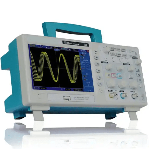
Features
- 200 MHz or 100 MHz or 60 MHz bandwidth
- 1GSa/s Real Time sample rate
- Large 7.0 in (17.78 cm) colour display, WVGA (800 x 480)
- Record length up to 2 M
- Trigger mode: edge/pulse width/line selectable video/slop/overtime etc.
- USB host and device connectivity, standard
- Multiple automatic measurements
- Four math functions, including FFTs standard
- VGA Optional
Technical Specifications
|
Sample Rate |
Real-Time Sample: 1GS/s |
|
Normal |
Normal data only |
|
Peak Detect |
High-frequency and random glitch capture |
|
Average |
Waveform Average, selectable 4,8,16,32,64,128 |
|
Inputs Coupling |
AC, DC, GND |
|
Inputs Impendence |
1 MΩ ± 2% II20 pF ± 3 pF |
|
Probe Attenuation |
1X, 10X |
|
Supported Probe Attenuation Factor |
1X, 10X, 100X, 1000X |
|
Maximum Input Voltage |
CAT I and CAT II: 300 VRMS (10×), Installation Category; |
|
Sample Rate Range |
500 MS/s to 1 GS/s |
|
Waveform Interpolation |
(sin x)/x |
|
Record Length |
2 M |
|
SEC/DIV Range |
2 ns/div to 40 s/div |
|
Sample Rate and |
±50 ppm (at over any ≥1 ms time interval) |
|
Position Range |
2 ns/div to 8 ns/div; 20 ns/div to 80 us/div; (-8 div x s/div) to 40 ms; |
|
Delta Time Measurement Accuracy |
Single-shot, Normal mode: ± (1 sample interval +100 ppm × reading + 0.6 ns); |
|
Vertical Resolution |
8-bit resolution, all channel sampled simultaneously |
|
Offset Range |
2 mV/div to 20 mV/div, ±400 mV; 50 mV/div to 200 mV/div, ±2 V |
|
Bandwidth |
200 MHz, 100 MHz, 60 MHz |
|
Rise Time at BNC (typical) |
1.8 ns, 3.5 ns, 5.8 ns |
|
Math |
+, -, ×, /, FFT |
|
FFT |
Windows: Hanning, Flattop, Rectangular, Bartlett, Blackman; |
|
Bandwidth Limit |
20 MHz |
|
Low Frequency Response (-3db) |
≤10 Hz at BNC |
|
DC Gain Accuracy |
±3% for Normal or Average acquisition mode, 10 V/div to 10 mV/div; |
|
DC Measurement Accuracy, |
When vertical displacement is zero, and N ≥16:± (3% × reading + 0.1div + 1mV) only 10 mV/div or greater is selected; |
|
Volts Measurement Repeatability, |
Delta volts between any two averages of ≥16 waveforms acquired under same setup and ambient conditions |
|
Trigger Types |
Edge, Video, Pulse, Slope, Over time, Alternative |
|
Trigger Source |
CH1, CH2, EXT, EXT/5, AC Line |
|
Trigger Modes |
Auto, Normal, Single |
|
Coupling Type |
DC, AC, Noise Reject, HF Reject, LF Reject |
|
Trigger Sensitivity |
DC(CH1,CH2): |
|
Trigger Level Range |
CH1/CH2: ±8 divisions from centre of screen; |
|
Trigger Level Accuracy(typical)Accuracy is for signals having risen and fall times ≥20ns |
CH1/CH2: 0.2 div × volts/div within ±4 divisions from centre of screen; |
|
Set Level to 50%(typical) |
Operates with input signals ≥50 Hz |
|
Video Trigger Type |
CH1, CH2: Peak-to-peak amplitude of 2 divisions; |
|
Signal Formats and Field Rates, Video Trigger Type |
Supports NTSC, PAL and SECAM broadcast systems for any field or any line |
|
Holdoff Range |
100 ns to 10 s |
|
Pulse Width Trigger Mode |
Trigger when (<, >, =, or ≠); Positive pulse or Negative pulse |
|
Pulse Width Trigger Point |
Equal: The oscilloscope triggers when the trailing edge of the pulse crosses the trigger level. |
|
Pulse Width Range |
20 ns to 10 s |
|
Slope Trigger Mode |
Trigger when (<, >, =, or ≠); Positive slope or Negative slope |
|
Slope Trigger Point |
Equal: The oscilloscope triggers when the waveform slope is equal to the set slope. |
|
Time Range |
20 ns to 10 s |


Reviews
There are no reviews yet.