Features
- 100 MHz bandwidths
- 1 GSa/s Real Time sample rate
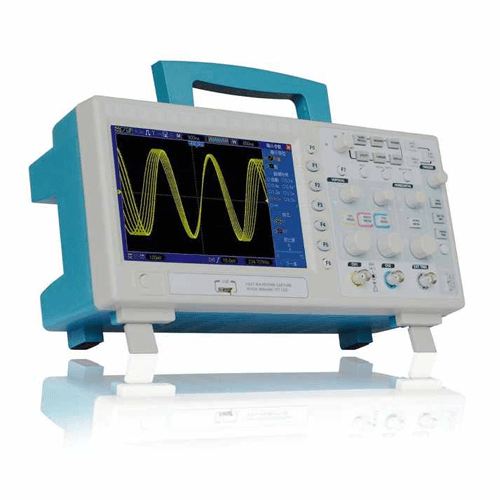
- Large 7.0 in (17.78 cm) color display,WVGA (800 pixels x 480 pixels)
- Record length up to 2 M
- 2 GB SD card and Video Help
- Trigger mode: edge/pulse width or line selectable video/slop/overtime etc.
- USB host and device connectivity, standard
- Multiple automatic measurements
- Four math functions, including FFTs standard
- Provides software for PC real-time analysis
- VGA Optional
Technical Specification
| Sample Rate | Real-Time Sample: 1 GS/s Equivalent Sample: 25 GS/s |
| Normal | Normal data only |
| Peak Detect | High-frequency and randon glith capture |
| Average | Waveform Average, selectable 4,8,16,32,64,128 |
| Inputs Coupling | AC, DC, GND |
| Inputs Impendance | 1 MΩ ±2% II20 pF ±3 pF |
| Probe Attenuation | 1X, 10X |
| Supported Probe Attenuation Factor | 1X, 10X, 100X, 1000X |
| Maximum Input Voltage | CAT I and CAT II: 300 VRMS (10×), Installation Category; CAT III: 150 VRMS (1×); Installation Category II: derate at 20 dB/decade above 100 kHz to 13 V peak AC at 3 MHz* and above. For non-sinusoidal waveforms, peak value must be less than 450 V. Excursion above 300 V should be of less than 100ms duration. RMS signal level including all DC components removed through AC coupling must be limited to 300 V. If these values are exceeded, damage to the oscilloscope may occur. |
| Sample Rate Range | 500 MS/s to 1 GS/s |
| Waveform Interpolation | (sin x)/x |
| Record Length | 2 M |
| Video Help | Yes |
| SD Card | 2 GB |
| SEC/DIV Range | 2ns/div to 40s/div |
| Sample Rate and Delay Time Accuracy |
±50 ppm (at over any ≥1ms time interval) |
| Position Range | 20 ns/div to 80 us/div; (-8div x s/div) to 40ms. 200 us/div to 40 s/div; (-8 div x s/div) to 400s |
| Delta Time Measurement Accuracy (Full Bandwidth) |
Single-shot, Normal mode: ± (1 sample interval +100ppm × reading + 0.6ns); >16 averages: ± (1 sample interval + 100ppm × reading + 0.4ns); Sample interval = s/div ÷ 200 |
| Vertical Resolution | 8-bit resolution, all channel sampled simultaneously |
| Offset Range | 2 m V/div to 20 mV/div, ±400 m V; 50 m V/div to 200 m V/div, ±2 V 500 m V/div to 2 V/div, ±40 V; 5 V/div to 10 V/div, ±50 V |
| Bandwidth | 200 MHz or 100 MHz or 60 MHz |
| Rise Time at BNC (typical) | 1.8 ns or 3.5 ns or 5.8 ns |
| Math | +, -, *, /, FFT |
| FFT | Windows: Hanning, Flattop, Rectangular, Bartlett, Blackman. 1024 sample point |
| Bandwidth Limit | 20 MHz |
| Low Frequency Response (-3db) | ≤10 Hz at BNC |
| DC Gain Accuracy | ±3% for Normal or Average acquisition mode, 10 V/div to 10m V/div; ±4% for Normal or Average acquisition mode, 5m V/div to 2m V/div |
| DC Measurement Accuracy, Average Acquisition Mode |
When vertical displacement is zero, and N ≥16: ± (3% × reading + 0.1 div + 1 mV) only 10mV/div or greater is selected. When vertical displacement is not zero, and N≥16: ± [3% × (reading + vertical position) + 1% of vertical position + 0.2 div]; Add 2 mV for settings from 2 mV/div to 200 mV/div; add 50 mV for settings from 200 mV/div to 10 V/div |
| Volts Measurement Repeatability, Average Acquisition Mode |
Delta volts between any two averages of ≥16 waveforms acquired under same setup and ambient conditions |
| Trigger Types | Edge, Video, Pulse, Slope, Over time, Alternative |
| Trigger Source | CH1, CH2, EXT, EXT/5, AC Line |
| Trigger Modes | Auto, Normal, Single |
| Coupling Type | DC, AC, Noise Reject, HF Reject, LF Reject |
| Trigger Sensitivity (Edge Trigger Type) |
DC (CH1, CH2): 1div from DC to 10 MHz; 1.5 div from 10 MHz to 100 MHz; 2div from 100 MHz to Full; DC (EXT): 200 mV from DC to 100 MHz; 350 mV from 100 MHz to 200 MHz; DC(EXT/5): 1V from DC to 100 MHz;1.75V from 100 MHz to 200 MHz; AC: Attenuates signals below 10 Hz; HF Reject: Attenuates signals above 80 kHz; LF Reject: Same as the DC-coupled limits for frequencies above 150 kHz; attenuates signals below 150 kHz |
| Trigger Level Range | CH1/CH2: ±8 divisions from center of screen. EXT: ±1.2 V; EXT/5: ±6 V |
| Trigger Level Accuracy(typical)Accuracy is for signals having risen and fall times ≥20ns | CH1/CH2: 0.2div × volts/div within ±4 divisions from center of screen. EXT: ± (6% of setting + 40 mV). EXT/5: ± (6% of setting + 200 mV). |
| Set Level to 50%(typical) | Operates with input signals ≥50 Hz |


Reviews
There are no reviews yet.