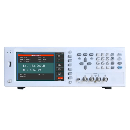
Overview
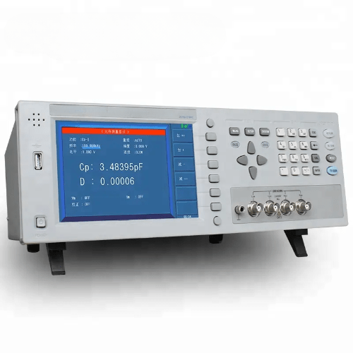
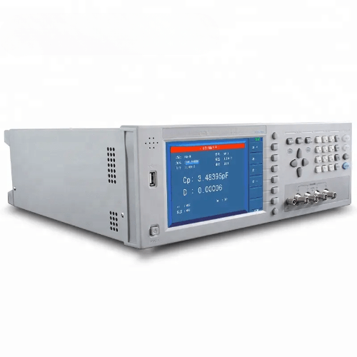
Emissions And Stack high frequency LCR digital bridge meter is a multi-functional component tester for testing all kinds of electronic components. The most popular 7 in (17.78 cm) 800 x 480 color TFT LCD display is adopted, it is more intuitive and more comfortable for users to read test results. It is an impedance meter with high speed, wide test range and 6-bit test resolution. The instrument can meet the requirements of production line quality assurance, purchase inspection and laboratory measurement. The main test products include microphones, resonators, inductors, ceramic capacitors, liquid crystal displays, varactor diodes, transformers, etc. Interfaces such as Handler, RS232C, USB, GPIB and perfect command system provided by the instrument can help users easily set up a test system.
Features
- 4 parameter display
- 7 in (17.78 cm) 16: 9 TFT LCD display
- Accuracy is 0.05%, the maximum test speed can reach 50 t/s
- Automatic level control ALC function
- 4 different signal sources output impedance
- Built-in comparator, 10 file sorting and file counting function
- 10 points list scan function
- Internal OV, 1.5 V, 2V DC bias voltage source
- Internal 100 setting files for storage or call
- Upgraded and updated by USB HOST
- U disk can support file systems with FAT16, FAT32 format
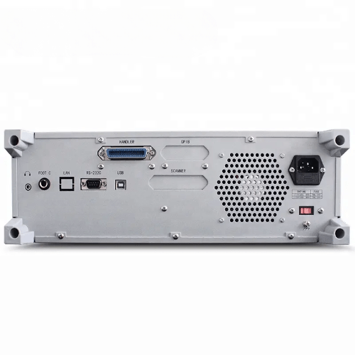
- Standard interface RS232C, HANDLER, USB HOST etc
Technical Specifications
| Measurement function | |
| Test parameters | IZI, IYI, C, L, X, B, R, G, D, Q, 8, DCR |
| Basic measurement accuracy | 0.05% |
| Equivalent Circuit | Series, parallel |
| Math function | Absolute deviation, Percentage deviation |
| Range method | Automatic, Hold, Manual selection |
| Trigger mode | Internal, Manual, External, Bus |
| Measurement speed(≥1kHz)
|
Fast speed: 50 t/s, Medium speed: 12 t/s, Slow speed: 3 t/s |
| Average time | 1 to 255 |
| Delay time | 0 s to 60 s, 1 ms as step |
| Correction function | Open circuit or short circuit or load |
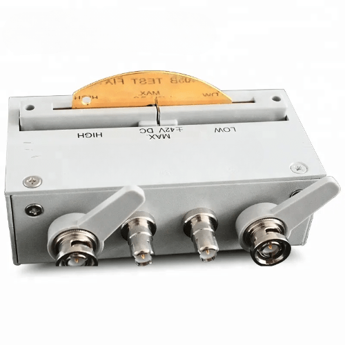
| Test end configuration | Five ends |
| List scan | 10 points list scan function |
| Display mode | Direct reading, A, A%, V or I (Measured voltage or current monitoring) |
| Display test signal | 800 x 480 RGB 7 in (17.78 cm) 16: 9 TFT LCD display |
| Output resistance | 30, 100 Q, 50, 10 or CC optional |
| Test signal level | normal: 5 mV to 2 V, 1 mV step constant level: 10 mV to 1 V, 1 mV step |
| Others | |
| Comparator function | 10 bins, BIN1 to BIN9, PASS or FAIL Display, NG, AUX |
| Memory | 10 groups of internal setting files for storage or recall |
| Interface | Standard RS232C, HANDLER, USB HOST, headphone interface, optional GPIB, LAN interface |
| Display range | |
| IZI, R, X | 0.01 m2 to 99.99 MQ |
| DCR | 0.01 m2 to 99.99 MQ |
| IYI, G, B | 0.00001 us to 99.99 S |
| C | 0.00001 pF to 9.99 F |
| L | 0.00001 μH to 9999.99 H |
| D | 0.00001 to 9.99 |
| Q | 0.00001 to 9999.9 |
| e (DEG) | -179.99° to 179.99° |
| e (RAD) | -3.14 to 3.14 |
| Others | |
| Comparator function | 10 bins, BIN1-BIN9, PASS or FAIL Display, NG, AUX |
| Memory | 10 groups of internal setting files for storage or recall |
| Interface | Standard RS232C, HANDLER, USB HOST, headphone interface, optional GPIB, LAN interface |