Overview
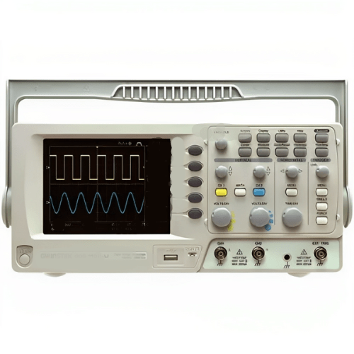
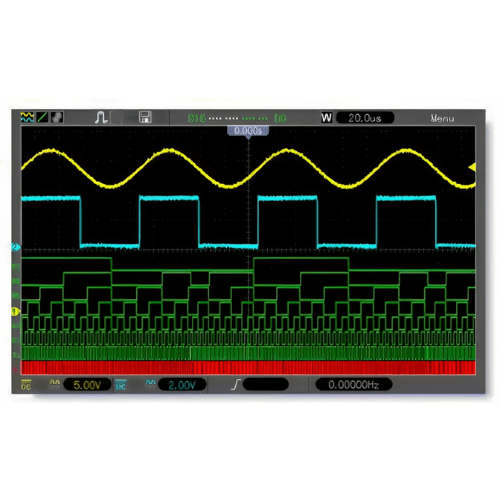
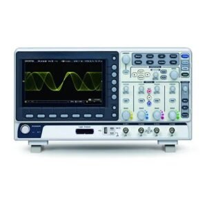
Emissions And Stack oscilloscope logic analyzer has 8 Channel Logic Analyzer; 25 MHz Arb. Waveform Generator; Large 7 in (17.7 cm) 64K color Display, WVGA: 800 pixels × 480 pixels.
Features
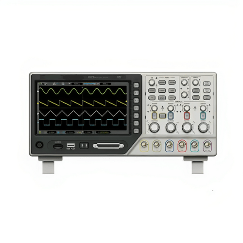
- 4 Channel Oscilloscope +8 Channel Logic Analyzer + 25 MHz Arb
- Abundant Trigger type: Video, Edge, Slope, Pluse Width, Overtime
- Alternative, Code-type, Duration, Queue, Repeat trigger
- Large 7 in (17.7 cm) 64 K color Display, WVGA: 800 pixels × 480 pixels
- USB host and device connectivity, standard
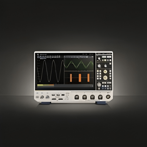
- Ultrathin design, handy volume, easily portable
Technical Specification
| Bandwidth | 300 MHz, 200 MHz, 100 MHz, 80 MHz |
| Real Sample Rate | 2 GSa or s |
| Memory Depth | 32 K |
| Time Base Range (S Or Div) | 2 ns or div to 40 s or div
4 ns or div to 40 s or div |
| Delay Time Accuracy | 500 PS |
| Vertical Resolution | 8 bits |
| Volts Or Div Range | 2 mV or div to 5V or div |
| Position Range | ±50 V (5 V to div), ±40 V (2 V to div to 500 mV to div), ±2V (200 mV or div to 50 mV or div) ±400 mV (20 mV or div to 2 mV or div) |
| Rise Time | ≤1.2 ns, ≤1.8 ns, ≤3.5 ns, ≤4.4 ns |
| DC Gain Accuracy | ±3% for Normal or Average acquisition mode, 5 V or div to 10 mV or div; ±4% for Normal or Average acquisition mode, 5 mV or div to 2 mV or div |
| Trigger Source | CH1, CH2, EXT, EXT or 5, AC Line |
| Trigger Modes | Auto, Normal, Single |
| Trigger Sensitivity (Edge Trigger Type) |
DC (CH1, CH2, CH3, CH4): 1div from DC to 10 MHz; 1.5 div from 10 MHz to 100 MHz; 2 div from 100 MHz to Full; AC: Attenuates signals below 10 Hz; HF Reject: Attenuates signals above 80 kHz; LF Reject: Same as the DC-coupled limits for frequencies above 150 kHz; attenuates signals below 150 kHz |
| Trigger Level Range | CH1, CH2, (CH3, CH4): ±8 divisions from center of screen; EXT: ±1.2 V; EXT or 5: ±6 V |
| Trigger Level Accuracy | CH1, CH2, (CH3, CH4): 0.2 div × volts or div within ±4 divisions from center of screen; EXT: ± (6% of setting + 40 mV); EXT or 5: ± (6% of setting + 200 mV); |
| Hold Off Range | 100 ns to 10 s |
| Channels | 8 Channel |
| Max. Input Impendence | 200 K (C=10 p) |
| Input Voltage Range | 0 V to 3 V |
| Max. Sample Rate | 1GSa or s |
| Compatible Input | TTL, CMOS, ECL |
| Sample Depth | 32 K |
| Wave frequency | DC to 25 MHz |
| Dac clock | 2 K to 200 MHz adjustable |
| Frequency Accury | 0.10% |
| Waveform Length | 4 KSa |
| Vertical Resolution | 12 Bit |
| Frequency Stabilization | <30 ppm |
| Amplitude | ±3.5 V Max. |
| Output Impedance | 50 Ω |
| Output current | 50 mA I peak=50mA |
| System Bandwidth | 25M |
| Wave Distortion | -50 dBc (1 KHz), -40 dBc (10 KHz) |
| Frequency Area | DC to 50 MHz |
| Input Amplitude | 400 mVpp to 18 Vpp |
| Coupling | DC |
| Frequency precision | ±Time Base Error ±1 Count |
| Input Impedance | > 100 KΩ |
| Pattern generator | 12 Bit |
| Supply Voltage | 100 VACRMS to 120 VACRMS (±10%), 45 Hz to 440 Hz, CATⅡ; 120 VACRMS to 240 VACRMS (±10%), 45 Hz to 66 Hz, CATⅡ |
| Power Consumption | <30 W |
| Fuse | 2 A, T rating, 250 V |
| Display | 7 in (17.7 cm) 64K color TFT LCD, (WBGA 800 pixels × 480 pixels) |
| Dimension | 12.3 in × 4.2 in × 5.5 in (313 mm x 108 mm x 142 mm) |
| Weight | 5.5 lb (2.5 kg) |


Reviews
There are no reviews yet.