Overview
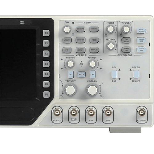
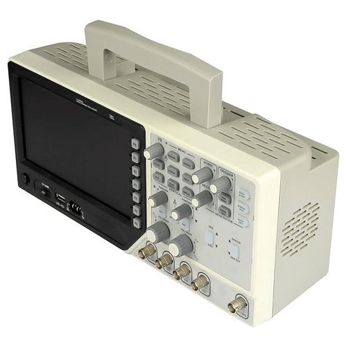
Emissions And Stack function generators are separated for convenient to operate it simultaneously. Oscilloscope: 200 MHz, 100 MHz, 70 MHz Bandwidth, 1 Ga/s Sample Rate. 25 MHz Arbitrary waveform generator, 12 bits resolution, 200 MHz DDS, 7 in (17.78 cm) 64 K color LCD display, Resolution 800×480.Channel Digital Oscilloscope +Arbitrary Function Waveform Generator + Synchronizing Signal + External Trigger; The Keys for oscilloscope and waveform generator is separated for convenient to operate it simultaneously; Large and clear display (7 in (17.78 cm) 64 K color LCD display, Resolution 800×480), more clear and realistic waveform; Oscilloscope: 1GSa/s Sample Rate, 200 MHz, 100 MHz, 70 MHz Bandwidth, more than 20 kinds of auto measurement functions; Powerful Trigger Function: Edge, Video, Pulse, Slope, Over time, Alternative; Arbitrary Function Waveform Generator: 25MHz, 12 bits resolution, 200MHz DDS, Arbitrary wave square wave sine wave triangle wave trapezoidal wave pulse wave DC is easy to simulate transducer. Support SD card, VGA function (optional); Integrated USB Host, Support USB disk storage, USB interface or SD card system update.
Technical Specifications
| Sample Rate | Sampling Rate Range: 1 Ga/s
Equivalent Sample Rate: 25 Ga/s |
|
| Acquisition Modes | ||
| Normal | Normal data only | |
| Peak Detect | High frequency and random glitch capture | |
| Average | Waveform Average, selectable 4,8,16,32,64,128 | |
| Inputs Coupling | AC, DC, GND | |
| Inputs Impedance | 1 MΩ ±2 % 20 pF±3 pF | |
| Probe Attenuation | 1 x, 10 x | |
| Supported Probe Attenuation Factor | 1 x, 10 x, 100 x, 1000 x | |
| Maximum Input Voltage | CAT I and CAT II: 300VRMS (10×)
CAT III: 150 V RMS (1×) |
|
| Sample Rate Range | 1 GS/s | |
| Waveform Interpolation | (sin x) or x | |
| Record Length | 40 K | |
| SEC or DIV Range | 2 ns or div to 40 s or div, 4 ns or div to 40 s or div | |
| Sample Rate and
Delay Time Accuracy |
±50 ppm at over any ≥1 ms time interval) | |
| Position Range | 2 ns or div to 10 ns or div;
20 ns or div to 80 u or div; (-8 div x s or div) to 40 ms; (-4 div x s or div) to 20 ms; 200 us or div to 40 s or div; (-8 div x s or div) to 400 s |
|
| Delta Time Measurement Accuracy (Full Bandwidth) | Single shot, Normal mode: ± (1 sample interval +100 ppm × reading + 0.6 ns); >16 averages: ± (1 sample interval + 100 ppm × reading + 0.4 ns); Sample interval = s or div ÷ 200 |
|
| Vertical | ||
| Vertical Resolution | 8-bit resolution, all channel sampled simultaneously | |
| Position Range | 2 mV or div to 10 V or div | |
| Bandwidth | 200 MHz,100 MHz,70 MHz | |
| Rise Time at BNC (typical) | 1.8 ns,3.5 ns,5 ns | |
| Analog Bandwidth in Normal and Average modes at BNC or with probe, DC Coupled | 2 mV or div to 20 mV or div, ±400 mV; 50 mV or div to 200 mV or div, ±1V
500 mV or div to 2 V or div, ±40 V; 5 V or div, ±50 V |
|
| Math | +, -, x, or FFT | |
| FFT | Windows: Hanning, Flattop, Rectangular, Bartlett, Blackman;
1024 sample point |
|
| Bandwidth Limit | 20 MHz | |
| Low Frequency Response (-3db) | ≤10 Hz at BNC | |
| DC Gain Accuracy | ±3% for Normal or Average acquisition mode, 5 V or div to 10 mV or div;
±4% for Normal or Average acquisition mode, 5 mV or div to 2 mV or div |
|
| DC Measurement Accuracy, Average Acquisition Mode |
When vertical displacement is zero, and N ≥16:± (3% × reading + 0.1 div + 1 mV) only 10 mV or div or greater is selected; When vertical displacement is not zero, and N ≥16: ± [3% × (reading + vertical position) + 1% of vertical position + 0.2 div]; Add 2 mV for settings from 2 mV or div to 200 mV or div; add 50 mV for settings from 200 mV or div to 5 V or div | |
| Volts Measurement Repeatability, Average Acquisition Mode | Delta volts between any two averages of ≥16 waveforms acquired under same setup and ambient conditions | |
| Trigger System | ||
| Trigger Types | Edge, Video, Pulse, Slope, Over time, Alternative | |
| Trigger Source | CH1, CH2, EXT, EXT or 5, AC Line | |
| Trigger Modes | Auto, Normal, Single | |
| Coupling Type | DC, AC, Noise Reject, HF Reject, LF Reject | |
| Trigger Sensitivity (Edge Trigger Type) |
DC (CH1, CH2):
1div from DC to 10 MHz; 1.5 div from 10 MHz to 100 MHz; 2 div from 100 MHz to Full; DCEXT): 200 mV from DC to 100 MHz; 350 mV from 100 MHz to 200 MHz; DCEXT or 5): 1 V from DC to 100 MHz;1.75 V from 100 MHz to 200 MHz; AC: Attenuates signals below 10 Hz; HF Reject: Attenuates signals above 80 kHz; LF Reject: Same as the DC coupled limits for frequencies above 150 kHz; attenuates signals below 150 kHz |
|
| Trigger Level Range | CH1 or CH2: ±8 divisions from center of screen;
EXT: ±1.2 V EXT or 5: ±6 V |
|
| Trigger Level Accuracy(typical)Accuracy is for signals having risen and fall times ≥20 ns | CH1 or CH2: 0.2div × volts or div within ±4 divisions from center of screen;
EXT: ± (6 % of setting + 40 mV); EXT or 5: ± (6 % of setting + 200 mV); |
|
| Set Level to 50 %(typical) | Operates with input signals ≥50 Hz | |
| Video Trigger | ||
| Video Trigger Type | CH1, CH2: Peak to peak amplitude of 2 divisions;
EXT: 400 mV; EXT or 5: 2 V |
|
| Signal Formats and Field Rates, Video Trigger Type | Supports NTSC, PAL and SECAM broadcast systems for any field or any line | |
| Holdoff Range | 100 ns to 10 s | |
| Pulse Width Trigger | ||
| Pulse Width Trigger Mode | Trigger when (<, >, =, or ≠); Positive pulse or Negative pulse | |
| Pulse Width Trigger Point | Equal: The oscilloscope triggers when the trailing edge of the pulse crosses the trigger level. Not Equal: If the pulse is narrower than the specified width, the trigger point is the trailing edge. Otherwise, the oscilloscope triggers when a pulse continues longer than the time specified as the Pulse Width. Less than: The trigger point is the trailing edge. Greater than (also called overtime trigger): The oscilloscope triggers when a pulse continues longer than the time specified as the Pulse Width |
|
| Pulse Width Range | 20 ns to 10 s | |
| Slope Trigger | ||
| Slope Trigger Mode | Trigger when (<, >, =, or ≠); Positive slope or Negative slope | |
| Slope Trigger Point | Equal: The oscilloscope triggers when the waveform slope is equal to the set slope.
Not Equal: The oscilloscope triggers when the waveform slope is not equal to the set slope. Less than: The oscilloscope triggers when the waveform slope is less than the set slope. Greater than: The oscilloscope triggers when the waveform slope is greater than the set slope. |
|
| Time Range | 20 ns to 10 s | |
| Overtime Trigger | ||
| Over Time Mode | Rising edge or Falling edge | |
| Time Range | 20 ns to 10 s | |
| Alternative Trigger | ||
| Trigger on CH1 | Internal Trigger: Edge, Pulse Width, Video, Slope | |
| Trigger on CH2 | Internal Trigger: Edge, Pulse Width, Video, Slope | |
| Trigger Frequency Counter | ||
| Readout Resolution | 6 digits | |
| Accuracy (typical) | ±30 ppm (including all frequency reference errors and ±1 count errors) | |
| Frequency Range | AC coupled, from 4 Hz minimum to rated bandwidth | |
| Signal Source | Pulse Width or Edge Trigger modes: all available trigger sources
The Frequency Counter always measures trigger source, including when the oscilloscope acquisition pauses due to changes in the run status, or acquisition of a single shot event has completed. Pulse Width Trigger mode: The oscilloscope counts pulses of significant magnitude inside the 1 s measurement window that qualify as triggerable events, such as narrow pulses in a PWM pulse train if set to < mode and the width is set to a relatively small time. Edge Trigger mode: The oscilloscope counts all edges of sufficient magnitude and correct polarity. Video Trigger mode: The Frequency Counter does not work. |
|
| Measure | ||
| Cursor Measurement | Voltage difference between cursors: V
Time difference between cursors: T Reciprocal of T in Hertz (1 or ΔT) |
|
| Auto Measurement | Frequency, Period, Mean, Pk Pk, Cycli RMS, Minimum, Maximum, Rise time, Fall Time,
+Pulse Width, Pulse Width, Delay1 2Rise, Delay1 2Fall, +Duty, Duty, Vbase, Vtop, Vmid, Vamp, Overshoot, Preshoot, Period Mean, Period RMS, FOVShoot, RPREShoot, BWIDTH, FRF, FFR, LRR, LRF, LFR, LFF |
|
| Waveform Impedance | DC or 25 MHz | |
| Sample Rate | 200 MHz DDS | |
| Output Waveform | Arbitrary wave or square wave or sine wave or triangle wave or trapezoidal wave or pulse wave or DC | |
| Frequency Resolution | 0.1% | |
| Waveform Depth | 4 KSa | |
| Vertical Resolution | 12 bits | |
| Frequency Stability | <30 ppm | |
| Waveform Range | ±3.5 V Max | |
| Output Impedance | 50 | |
| Output Current | 50 mA I peak=100 mA | |
| System BW | 25 M | |
| Harmonic Distortion | -50 dB 1 KHz -40 dB 10 KHz | |
| Display Type | 7 in (17.8 cm) 64 K color TFT (diagonal liquid crystal) | |
| Display Resolution | 800 horizontals by 480 vertical pixels | |
| Display Contrast | Adjustable (16 gears) with the progress bar | |
| Probe Compensator Output | ||
| Output Voltage(typical) | About 5 Vpp into ≥1 MΩ load | |
| Frequency(typical) | 1 kHz | |
| Power Supply | ||
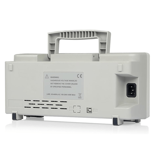
| Supply Voltage | 100 V to 120 V AC RMS (±10%), 45 Hz to 440 Hz, CAT II
120 V to 240 V AC RMS (±10%), 45 Hz to 66 Hz, CATII |
|
| Power Consumption | <30 W | |
| Fuse | 2 A, T rating, 250 V | |
| Environmental | ||
| Temperature | Operating: 32 °F to 122 °F (0 ℃ to 50 ℃);
Nonoperating: -40 °F to 159.8 °F (-40 ℃ to +71 ℃) |
|
| Cooling Method | Convection | |
| Humidity | +104 or below (+40 or below): ≤90% relative humidity;
106 °F to 122 °F (+41 ℃ to 50 ℃): ≤60% relative humidity |
|
| Altitude | Operating: Below 10,000 ft (3,000 m);
Nonoperating: Below 50,000 ft (15,000 m) |
|
| Mechanical | ||
| Size | Length 15.1 in (385 mm), Width 7.87 in (200 mm), Height 9.64 in (245 mm) | |
| Weight | 77.1 lb (3.5 Kg) (with Packing); 4.6 lb (2.08 Kg) (without Packing | |


Reviews
There are no reviews yet.